Have you wanted to learn more about Sikla Building Information Modelling (BIM) tools? Specifically, the PDMS / E3D (Plant Design Management System) plugin software?
Originally posting to the Sikla UK and Sikla Oceania LinkedIn pages, in this blog you will discover and learn the 9 key PDMS/E3D tools to optimise your next BIM project by watching the videos below.
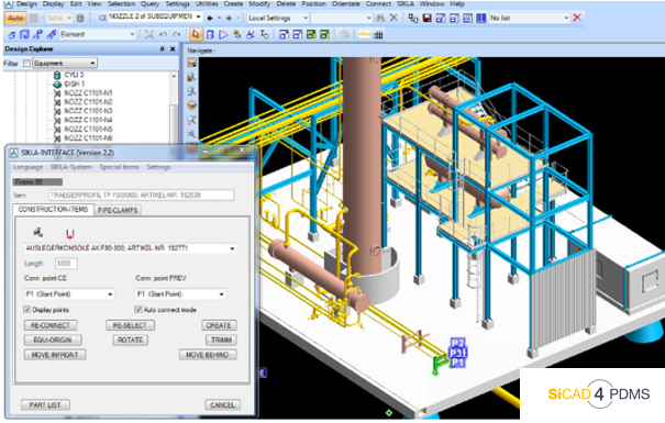
PDMS / E3D is a 3D CAD software used for large-scale engineering, design and construction projects for pipe structure planning with accuracy. The Sikla interface SiCAD4PDMS / E3D is available for PDMS or E3D from AVEVA GmbH. In the UK construction industry, BIM software is becoming more important to optimise each stage of a large-scale project. As a digital representation, users of 3D BIM software can plan and design projects with relevant data on materials and components.
Start becoming an expert in using the PDMS / E3D plugin software today. Watch our 9 demonstration videos on how to use the SiCAD4PDMS/ E3D tools to help with your BIM design project.
- Video 1: ATTA Designer
- Video 2: Template Designer, Part 1
- Video 3: Template Designer, Part 2
- Video 4: Part by Part Designer - Connection to Steel
- Video 5: Part by Part Designer - Connection to Concrete
- Video 6: Connection Designer
- Video 7: Consistency Check
- Video 8: Revision Manager
- Video 9: Sikla Reports (MTO)
Video 1: ATTA Designer
This demonstration of the ‘ATTA’ designer tools showcases a semi-automated tool to add primary supports (i.e. pipe shoes & guides, also known as an ATTA in the software) from the Sikla library to a designed pipeline.
Key moments to remember:
- Adding a pipe shoe, matching the pipe size and elevation
- Switching a fixed point shoe, to an assembly group, then to a sliding guide
Video 2: Template Designer, Part 1
Template Designer is a PDMS/E3D tool used to create secondary supports (i.e. pipe support structures, like siFramo), using pre-set template arrangements (e.g. goal post, T-Posts, L-Brackets).
The 2 key parts of this video are:
Creating a goal post using 3 points of selection:- First main structure
- ATTA
- Second main structure
Adding a second tier to the goal post using 3 points of selection:
- First goal post upright
- ATTAs
- Second goal post upright
Video 3: Template Designer, Part 2
A continuation of video 2, here you can see how to use the edit function in the template designer to modify the position of the goal post uprights, then swap the components used to make up the crossbar.
Focus on these key moments:
- Re-selecting the goal post for modifications, then moving the 1st goal post upright 500mm from the original position
- Selecting the crossbar for modification, swapping the left-hand connection from a beam section + STA, to an AK Cantilever
Videos 4: Part by Part Designer - Connection to Steel
A semi-automated tool to create secondary supports (i.e., pipe support structures, like siFramo) when no suitable template can be used.
Key moments of this video:
- Add a vertical supporting member with top and bottom clamps to the primary steel
- Add a crossbar, supported at the bottom by a clamped connection to the primary steel
- Finally, modify this crossbar connection to extend the vertical upwards and clamp to primary steel at the top
Video 5: Part by Part Designer - Connection to Concrete
A semi-automated tool to create secondary supports (i.e., pipe support structures, like siFramo) when no suitable template can be used for connections to concrete.
The key takeaways in this video:
- Shows the user constructing an atypical design in a handful of clicks in BUILD mode
- Removes the unwanted crossbar that clashes with the concrete using the SUBTRACT mode
- Finally updating the frame to give the correct backplate and fixation to concrete (using the CONNECT button)
Video 6: Connection Designer
A tool used to translate rough or pre-planned designs into working secondary supports (i.e. with the correct Sikla connections, like STAs, WBDs and correct beam lengths).
What is the most valuable takeaway here?
Selecting the pre-planned structure (STRU) and using the ✨MAGIC WAND tool to intelligently and automatically translate the rough design into a siFramo frame, clamped to the primary steel.
Video 7: Consistency Check
The Consistency Check tool allows designers to check their modelling for incompatible connections, or improve their designs by suggesting alternative Sikla components.
What are the key moments of this video?
- Showing the list of pre-set rules which can be selected for use within the intelligent consistency check
- Resolving incompatible primary support by selecting an alternative option within the drop-down of the 'ATTA DESIGNER' module (via a convenient button to open the module directly within the consistency check)
- Resolving an incompatible steelwork connection (because the primary steel has been revised) by selecting one of the suggested connections from the drop-down within the 'Connection Designer' (via a convenient button to open the module directly within the consistency check)
- Re-running the consistency check for the updated support (all errors resolved) and finally addressing the suggestion to swap one of the two STA's end plate connections to a Sikla AK cantilever bracket (for a stronger crossbar connection). The consistency check is then re-run for a final time and is empty
Video 8: Revision Manager
With the Revision Manager tool, designers can modify an existing plug-in design to be Revised up and a description of the Rev is given.
Key moments of the video?
- A new strap is added to the existing Sikla design by opening the Part-by-Part designer and selecting the existing design. The Part-by-Part designer creates a new strap consisting of an STA, a beam section and a WBD with a clamping set. When Finish is pressed, the design update is complete
- After SU-0001 FRAMW is selected, the plug-in revision tool is opened. The current revision status is listed, with a description. The user enters a description for the new strap and presses 'Create New Revision'. A new revision appears listed in the Revision table
Video 9: Sikla Reports (MTO)
The Sikla Reports tool allows designers to create a fast and accurate bill of materials to Excel and/or produce an on-screen MTO for modellers to verify their designs.
What are the key moments of this video?👇
- For on-screen reports, the reporting tool is opened and a single Sikla framework is added to the input list by drag and drop. Options such as the report language and units of measure can be selected. For this demo, the on-screen output is selected to create a basic on-screen report
- For Excel reports, the tool is opened and multiple Sikla frameworks are added to the input list by drag and drop at the structure level. Specific output options are selected and saved as a Microsoft Excel template
CAD Implementation - Training & Guidance
Do you need any further guidance about these resources?
Sikla offers several tools and services capable of helping you:
- Specification Text Templates
- Software Plug-ins and CAD-libraries to implement Sikla components into detailed project design
- Structural calculation reports for worst-case designs (e.g. highest loads/temperatures)
Get familiar with these technical services and contact us for further consulting.

Written by Ross Smith
Senior Design Engineer IEng MIMechE
Comments