Thermal expansion is a central topic in the day-to-day work of Piping Engineers. Solving its challenges has been a core task to Sikla, delivering several pipe support solutions and detailed resources about the best practices for its applications. Read our Fixed Point Guidelines to successful pipe supports design.
You will access now a comprehensive technical guide, about how to select pipe supports for industrial piping and plant engineering.
About Pipe Expansion
When selecting and arranging the supports, the expansion of the pipes must be taken into account in addition to the fastening placement. In all areas of industry, and especially in mechanical engineering, project and assembly engineers are faced with the joint task of taking these expansions into account and controlling them.
Pipes for heating and process technology, in particular, are often subject to considerable temperature fluctuations and consequently show significant changes in length. The pipes shrink when they cool down and expand when they heat up. Depending on the material, pipelines expand very differently at the same temperature difference. Polyethylene (PE), for example, expands 17 times more than BS1387 steel pipe, therefore, the given coefficient of linear expansion must be taken into account during the planning phase due to the choice of material (see chart below).
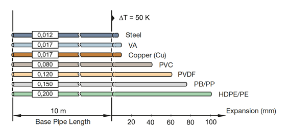
Material coefficient of linear expansion
So the fundamental fact is... Pipelines transport thermal energy over long distances, which highly increases the relevance of the design quality!
|
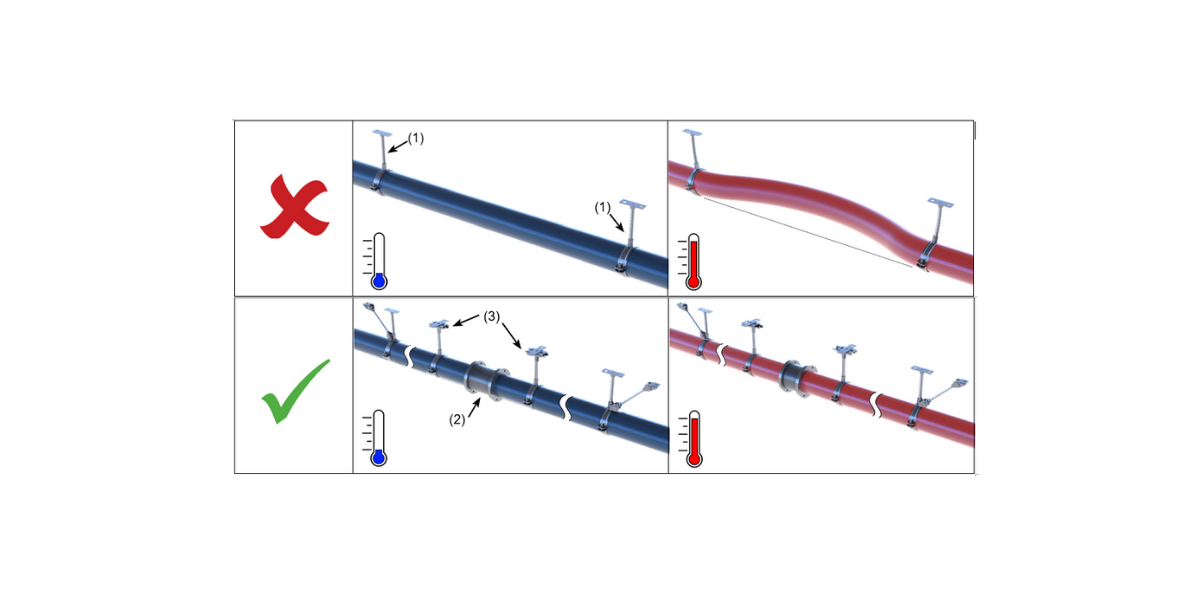
Whether a change in length is significant depends less on the absolute magnitude than on whether the pipeline has the possibility to yield to the change in length. |
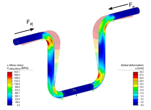
Mises stress distribution / deformation for U-bend |
In principle, the loop created by the change of direction are suitable for absorption. If these are not long enough to absorb the expansion elastically, even with well-considered pipe routing, expansion bends or compensators must be added. If these physical laws are not observed, the pipeline itself can be damaged and will cause serious damage to components or supports.
A change in length caused by a change in temperature requires different fixings in order to direct the movement in a targeted manner. This is necessary to prevent damage and to achieve high operational safety even under alternating loads. Correct planning and execution allow the pipeline to have freedom of movement at defined positions or to specifically prevent movement. Often the supports also have the task of absorbing weight forces of the pipeline.
What to have in mind when designing fastenings in the pipeline?
The positions for absorbing the weight forces are determined first. These already consider the support options on the structure, the spans based on the pipeline dimensions and the static dimensioning by pure weight force.
Subsequently, fixed points and guides are determined based on the expansion concept. (Otherwise, fixed points or guides at positions that cannot be realised on the structure entail further planning and design.)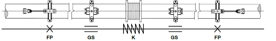
Fastenings in pipeline.
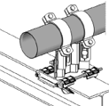
FP - Anchor points
Connect the pipe to the building structure, which is assumed to be rigid and can absorb forces and moments in all directions. This is known as the Primary Fixation. Since FP forces need to be taken into account, the design challenge is always high when the pipeline is planned with a large distance to the building structure. This soffit or wall distance greatly determines the FP design.
GS - Guide supports
Allow the pipeline to move in a predetermined direction but hinder it in another direction and they are usually equally spaced along the entire pipeline. The function is to prevent deflection of the pipe axis, while allowing the pipe to move in the axial direction.
LS - Non-locating support
It supports vertically acting loads, but not too significantly hinder displacements in the horizontal plane. These supports are often found in the area of directional changes and allow the desired deflection movement in expansion bends.
K - Expansion joints
Serve as flexible elements that absorb movement in the pipe system. They are used to compensate for changes in length, vibration decoupling or for pipe misalignments. Absorption of the movement takes place mechanically via elastic bellows.
And this is what you will achieve:
%20deforms%20during%20a%20temperature%20change..png?width=1080&name=Pipe%20with%20two%20fixed%20points%20(1)%20deforms%20during%20a%20temperature%20change..png) |
| Pipe with two fixed points (1) deforms during a temperature change. |
%20and%20steering%20by%20guide%20support%20(3)%20with%20temperature%20change.png?width=1078&name=Deformation%20stopped%20by%20expansion%20joint%20(2)%20and%20steering%20by%20guide%20support%20(3)%20with%20temperature%20change.png) |
| Deformation stopped by expansion joint (2) and steering by guide support (3) with temperature change |
Some Fixed Point Solutions and Examples
This Fixed Point Guide will show you in detail which types of pipe support to consider, depending on temperature changes, structural conditions, types of pipes or other requirements (as sound absorption).
There are different types of arrangements for each scenario, in addition to our Standard Range!
Here are a few practical examples of what you will find about:
|
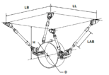
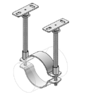
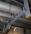
Trestle Arrangement - Spider Anchor |
Mounting without Bracing |
  |
  |
|
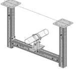
On siFramo Goal Post |
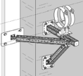
On siFramo with Pivot Joint |
  |
  |
|
On Steel Beam |
|
  |
How to optimize Fixed Point Calculation?
Sikla offers several tools to optimise the Fixed point calculation. According to the parameters (Fixed point force, pipe axis height, pipe diameter and Type), the most suitable assembly for the installation is found.
SiPlan: Fixed point module (Spider Anchors)
In the module of Siplan software"Fixed point", the fixed point force FP is determined at the L-bend and U-bend or when using an axial expansion joint and can be used for dimensioning the Trestle arrangement.
Sikla CAD-Library
The Sikla CAD library provides the Sikla entire product range, from the Siconnect and Simotec catalogues as 3D or 2D geometry in common formats.
Sikla Fixings Design Program
The anchor design program provides evidence for the usability of possible anchors according to the concrete load situation.
Sikla Anchor & Guide Range Matrix
A downloadable matrix where you can easily find all the available part numbers of Sikla Anchors and Guides range.
Get your Complete Fixed Point Guide now!
Download the Fixed Point technical guide now and get in touch with us for further and dedicated explanations to you and your design & planning team!
Comments