By Ross Smith on 29 June 2020
Within this blog series, we previously explained the key points of the siFramo modular steel framing system. In part 4, we will explore how much of the steel box section can really be used and discover 7 ways in which siFramo maximizes the available area to support services.
Why is it so important to make the most of the available space?
In any given industrial application, it is not uncommon to see banks of closely grouped services, be it pipes, cables or ducting, running seamlessly above our heads. It is easy to forget that even with the best planning and intentions, there may have been a need to accommodate 11th hour design changes. Such changes quickly swallow up any free space, reserved for future expansion.
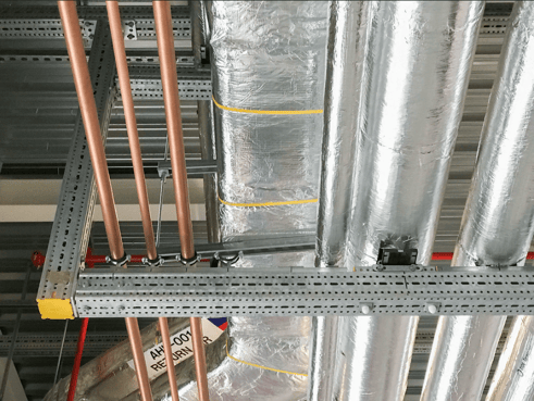
For this very reason, it is crucial for Sikla to be able to offer a solution that uses as much as of the space that is available. Do you want to know how the siFramo system offers this benefit?
Here we will cover 7 ways siFramo can optimise the use of the available space and maximize the use of the profile.
- From end-to-end (almost)
- With Flat Crossbars – T-Posts
- With Flat Crossbars – Cantilevers
- With Flat Crossbars – Assemblies
- By Keeping things Flush – A Level Surface
- By Keeping things Flush – As Close as Possible
- By Keeping things Flush - Alignment at the Top
1. From End-to-End (almost)
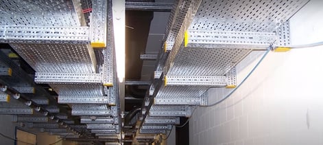
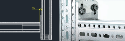
With its neat, square profile, the siFramo box section fits comfortably into many tight areas and provides a flat supporting surface, either 80mm or 100mm wide. When used in conjunction with the End Support STA (connected perpendicularly) almost all the supporting surface is vacant. This allows services to accommodate the length of the section as close as 15mm away from the connecting upright (a tolerance allotted for backing plates and screw heads).
2. With Flat Crossbars – T-Posts
Whilst the classic trapeze bracket configuration offers precise crossbar adjustment for those “Uh-oh” moments at site, it does not offer up the entire width of the frame as a supporting surface because of the inherent position of the uprights.
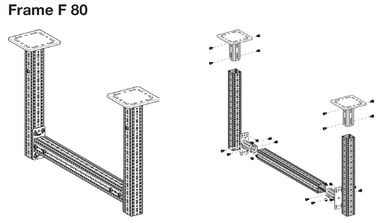 However, the beauty of the siFramo system lies in its square profile and interchangeable components which allow a frame to be configured in several ways. As well as being a flexible solution, siFramo allows a frame to be arranged to offer more surface area to support services.
Other classic frame arrangements, like the T-Post, are constructed with ease by securing a top crossbar to a central upright, freeing up the entire top surface for services or fixtures.
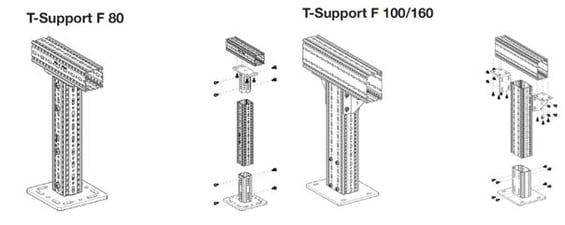
It is worth mentioning that these compact frames offer impressive load bearing capabilities for such relatively small designs. The F100/160 T-Post is capable of supporting single point loads of around 15kN (to put that into some context, that’s a 20-inch water-filled pipe, spanning 5m).
3. With Flat Crossbars – Cantilevers
Another simple and off the shelf solution is our pre-welded cantilever brackets, which offer up top and bottom surfaces for fixings, both above and below. As the end connection plate is welded, the entire length of the section is free from screws, allowing complete adjustability along the cantilever. Our cantilever brackets are available in 400, 600, 800 and 1200mm.
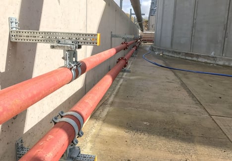
When supporting much higher loads, our TKO hollow-box-section, offers a very versatile and incredibly strong solution. Fixing the pre-welded 220 x 220mm square backing plate directly to building structures (4 x M12 anchors) allows all four surfaces of the TKO to support loads equally and in any plane of movement.
4. With Flat Crossbars – Assemblies
We can also pair brackets together to support even higher, dynamic loads and attach accessories, right up to the edge of the crossbar without deflection or overstressing the connection.
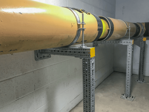
5. By Keeping things Flush – A Level Surface
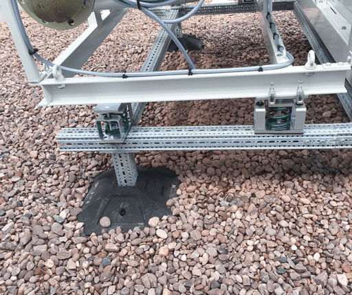
Volumetric loads? No problem. By orienting our STA end support downwards, we can create volumetric frames with multiple supporting members whilst maintaining a flush top of steel across the entire surface of the frame. Due to the square nature of the siFramo box section, not only is the top of steel flush in this arrangement, but also the bottom of steel, allowing supporting legs to be precisely positioned to transfer loads where required.
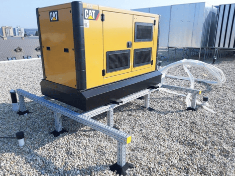
Maintaining a flush top of steel also allows load interfaces and points of contact to overlap crossing members, as the entire surface is level and free from screws or obstructions.
6. By Keeping things Flush – As Close as Possible
Need to install a frame but are tight on space? Our square beam sections fit flat to the wall and can be supported underfoot with an STA. This provides a flush upright connection whilst maintaining minimum clearances and reducing interference with free space or accessways.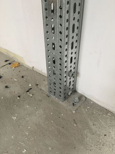
7. By Keeping things Flush – Alignment at the Top
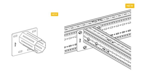 The siFramo framing system can be used to create load bearing structures which extend over large distances, for example a pipe bridge. Our heavy duty F100/160 box section allows long spans to be supported due to its increased cross-sectional rigidity. But what if your bents do not need this level of stiffness? Typically, crossmembers between supporting tramlines will require a lesser profile section. With the use of our offset STA end support connectors, it is possible to maintain a common top of steel (thus bottom of pipe) across an entire frame, even when reducing to smaller profile sizes.
So what is the answer?
So how much of the siFramo Steel section can be used as a support? When designing a frame with siFramo, there are several alternatives to explore and usually more than one suitable solution. The question is really, what are you supporting and how much space do you have? When we know this, siFramo can be configured to suit your needs, optimise the use of available space and maximise the use of the profile.
Coming up next - don't miss it:
- Can connections be made steplessly and fixing positions are not dependent on availability of holes and slots?
- Is independently tested load data available for all components and parts of the system?
- Is test data available for typical frame configurations and based on all 3 possible load directions?
- Is the system BIM and plant design software compatible?
- Can the system be calculated with a 3D structural frame analysis program?
- Is a global manufacturer accountable for the product?
Are you interested in the siFramo system and want to know more about how it could benefit your project?




Comments