By Sikla UK Oceania on 15 September 2020
Welcome back to our series of in-depth articles on the siFramo Modular Steel System.
In a previous article, we covered how to utilise the siFramo system’s Technical Guidelines and the typical frame configurations within. In this blog we will be discussing what can be done, such as structural analysis, if the design you are looking at is more complex than these typical arrangements.
Why might structural modelling software be required?
Whilst typical configurations are great and cover a large percentage of support positions, there are always instances where designs need an extra level of creativity. This is generally down to one or more of the following conditions:
- Limited or unavailable primary structure thereby limiting fixing opportunities
- Dynamic loading conditions (wind/live load/dynamic pipe forces)
- Service density and layout
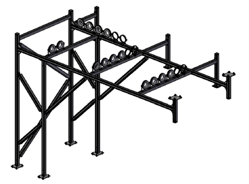
In the above situations, the designed support position can take on unusual geometry and be subject to dynamic loads from differing sources. In situations like this being able to utilize the appropriate structural modelling software is paramount to the checking and verification of the supports. For this purpose, the Sikla Group has partnered with Dlubal Software GmbH and use their structural modelling package RSTAB (learn more here about our software design tools). 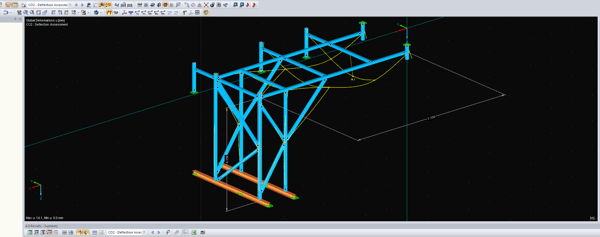
How does the structural modelling software work?
With RSTAB you can easily and quickly define a structural model and then calculate the internal forces, deformations, and support reactions. For further design, there are various add‑on modules available, considering structural data of specific materials and standards.
Internally we split the process up into three sections:
1. Modelling of the structure
2. Loading of the structure
3. Review of the structure
1. Modelling of the structure
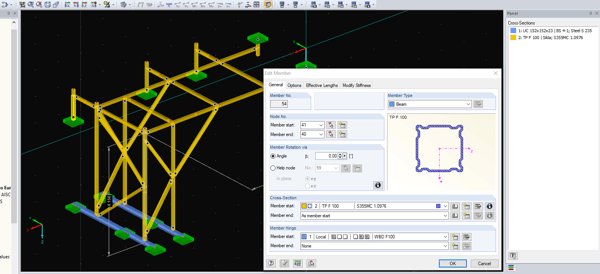
The first step is to model the structure. The software uses a node-based system that allows for the definition of members by both cross section and material grade. From there fixing positions and hinge definitions can be applied to simulate different components being used for each connection point.
2. Loading the structure
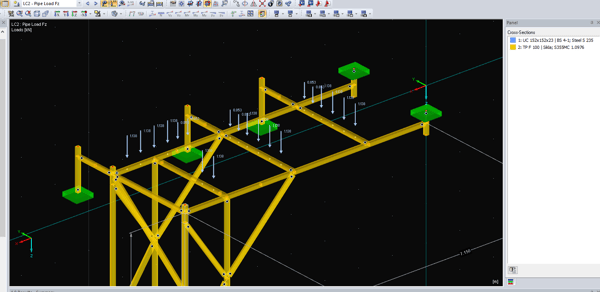
The next step is to create load cases for each type of load being applied to the frame. This may include things such as wind load, seismic load, dead load & dynamic pipe forces. Loads can be defined and applied anywhere along the structure in line with information from the client.
From these load cases, load combinations are created which apply multiple load cases to the frame at one time. For instance, the static load of the service can be acting on the frame in combination with the wind load generated by the surface area of the object.
3. Review of the structure
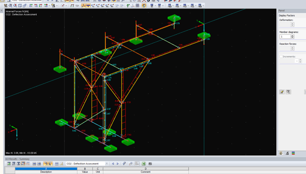
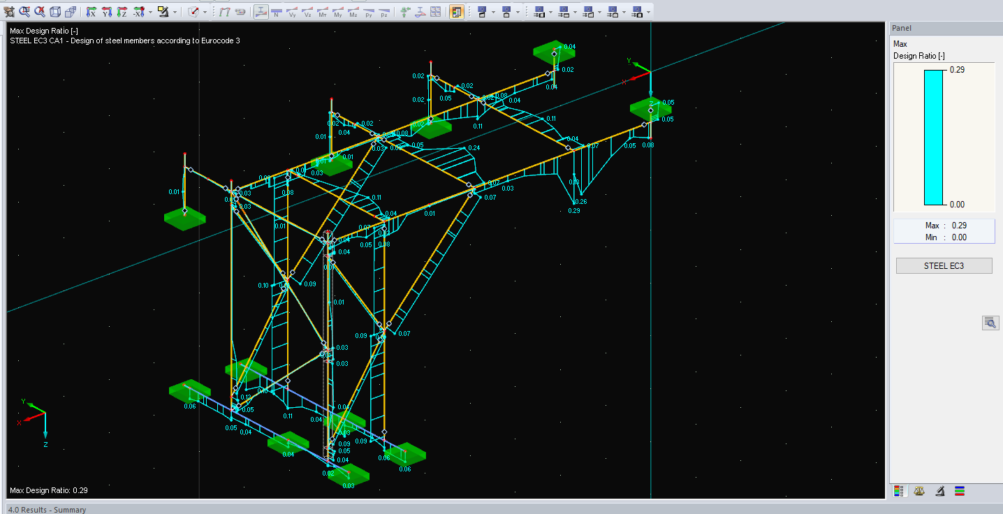
Once all the input data has been created from the previous two steps it is time to run and review the calculation. Individual component capacities are reviewed against the loads present. Section capacities are also reviewed in relation to the appropriate geographical code (EC3, AS 4100 etc). 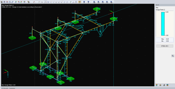
Output from this review process is then compiled into a report that can be sent to the client for review by their own engineering staff. These calculation reports can then form the basis for the technical sign-off of these complex structures.
So what does this mean for you?
Having confidence in the validity and safety of more complex designs is a key element in being able to supply large scale projects. With sound technical back up clients can rest assured that the siFramo system adheres to the proper design codes, and that the safety of both the project and those who work there will be secure!
Coming up next - don't miss it!
Are you and your team interested in learning more about the Modular Steel Framing System siFramo?
Contact us today, using the buttons above, or book your CPD training session HERE.
Written by Sikla UK Oceania



Comments