By Harry Starke on 18 May 2020
What was the initial goal of siFramo when it was launched?
Sikla developed a simple guide with 10 essential key points about the siFramo system, that can give an answer whether the system is suitable for your project or not.
The 1st question, explored in this article, addresses the member-to-member connection method and why modular steel design is more than just bolting an angle bracket to a perforated structure.
Starting Point: Solid, Welded Connection - NOT Another Bolted Frame
The application areas of our siFramo system are widespread and they nowadays go far beyond its original purpose: industrial pipe rack maintenance, modification and extension. It is worth remembering this because it was this starting point that defined one of the most important technical details in siFramo’s original FSD (Functional Specification Document): solidity and stiffness of member connections in all possible loading directions.
Without this crucial requirement a ‘supersize Unistrut’ would always have been enough. However, the performance benchmark is not another bolted frame, it is the strength of goal post, F-shaped and L-shaped pipe racks as the industry has been using it for the best part of a century.
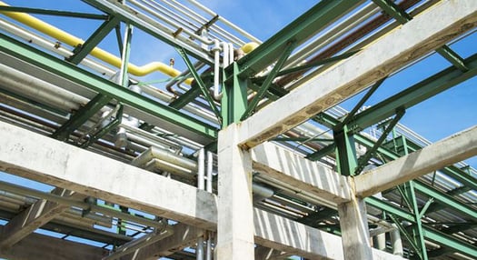
 Typical industrial pipe bridge made from traditional steel structures, requiring hot works and paint works for maintenance.
Squaring the Circle:
All-Embracing Connection but Attaching and Detaching Quickly
The big chemical and Oil & Gas plant owners used to have the choice between two evils. When loading was more relevant than flexibility, a steel frame requiring hot works and paintwork for both new built and maintenance was the only option. Likewise, when a flexible frame was chosen, load capacity used to be very restricted. The latter was made particularly unattractive considering the sustainability of the pipe rack, or lack thereof: in industrial plants it is usually expected that additional services may be added later.
Therefore, Sikla’s intention was to offer a solution to that dilemma. Anything other than a system that offers both high load bearing in all directions AND the removal of hot works and painting requirement would not have been the innovation that this market needed.

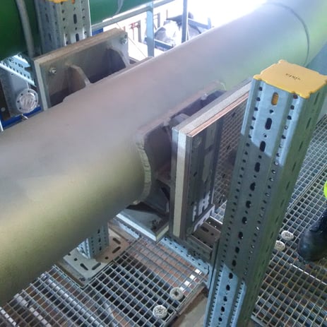
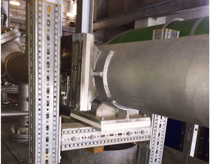
siFramo square circling in action: high load bearing in all directions but flexible, adjustable and with exchangeable components.
Is the Connection Method all About Loading?
If this were all about loading, surely a simple angle bracket, or a multiple arrangement with one bracket in each load direction would do it, at least if we drop time saving as an argument for a moment. However, there is another important requirement derived from traditional pipe rack design, one that applies to electrical containment alike: space management.
No doubt, a welded corner connection within a steel frame is not space consuming and does allow both a pipe shoe and a cable ladder to be placed right into the corner area. A connection based on bolted corner brackets on the other hand needs that area for, guess what, the corner bracket itself.
The conclusion is that a bolted steel frame based on corner brackets is either more space consuming because it needs to be designed wider or higher, or the corner areas cannot be used.
And This is Why the siFramo Connection is How it is
In steel design there are generally 3 routes to achieve additional strength:
- Dimension (material thickness, diameter, size);
- Quality (grade of base material)
- Geometry (shape of structures and connections)
siFramo is generally based on the principles of quality and geometry.
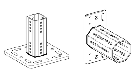
 Square and Octogonal end plates (End Support WBD and End Support STA) to apply at the end of beam section or bracket.
The member to member connections of the siFramo system are based on symmetrically shaped connectors that ‘plug into’ the section rather than being attached to the outside. There are square shaped and octagonally shaped components, a subject that will be addressed in another blog. As a result, the connection is equally strong in all directions by using just one standard component.
An angle bracket, as well as a webbing piece, are simpler products to design and an easier product to manufacture, the shape is comparably crude, and the manufacturing tolerances are generous enough to find fabricators quickly and globally. However, going back to the FSD, the original design brief, they lead to a system that misses one of its key details. Both angle brackets and webbing pieces support one part of the connection only and leave other parts of the same connection unsupported.
Therefore, angle brackets are too simple a connection method for a proper modular steel system, they may look strong but, like the Titanic’s fourth smoke funnel, are merely symbolic for power and safety
Coming up next - don't miss it:
- Are small parts safe against confusion, vibration and wrong application?
- Can a safe connection be spotted by the naked eye or does it require torque-wrenching to be sure?
- Do the connection elements keep the frame corners clear, i.e. 100% of section area can be used as a support?
- Can connections be made steplessly and fixing positions are not dependent on availability of holes and slots?
- Is independently tested load data available for all components and parts of the system?
- Is test data available for typical frame configurations and based on all 3 possible load directions?
- Can the system be calculated with a 3D structural frame analysis program?
- Is the system BIM and plant design software compatible?
- Is a global manufacturer accountable for the product?
Subscribe Sikla newsletter and follow our LinkedIn page to receive all the updates about these next articles.


Comments