In this blog series, we are taking an in-depth look at the siFramo Modular Steel System. In the previous article we discussed the siFramo system’s impressive ability to utilize as much space as possible in a variety of frame configurations. This blog focuses on flexible steel connections that goes hand in hand with the topic of space conservation and we will discuss the following questions:
- Can steel connections be made anywhere along the siFramo beam section?
- Why is this beneficial for you?
- If so, how is this possible?
- Is this still true of non-standard and non-Sikla components?
Can steel connections be made anywhere along the siFramo beam section?
To put it simply, YES, the siFramo system allows installers to make steel beam connections anywhere along the profile. There are no incremental fixing positions to worry about during the support design, no slot patterns to observe and therefore no controlled cuts need to be made. The siFramo system is a steel box section that has the same level of flexibility designed on all four sides of the profile. This allows for unlimited connection positions a long the profile for both two dimensional and volumetric supports for modular steel structures.
Why is this beneficial for you?
Having unrestricted fixing positions has major benefits in both the planning/design and installation phases.
During the planning phase it allows the designer to make the most of the space available by:
- Positioning services as close to one another as possible, without needing to align to the next slot/hole position.
- Positioning services as close to the edge of the supporting member as possible.
- Removing the consideration of controlled cuts for supporting members.
- Providing fixing positions on all four sides of the profile simultaneously (no through-bolts).
During the installation phase it enables the installer to cater to on-site adjustments by:
- Allowing finite adjustment to suit on-site conditions such as primary structure tolerances.
- Providing flexibility for unexpected service repositioning.
- Allowing for fixation of additional services to any of the available faces of the box section.
How does the siFramo system achieve this?
The big question at this point is, how has the siFramo system been designed in a way to make this possible? It boils down to the combination of two simple elements:
- The slot/hole pattern of the profile
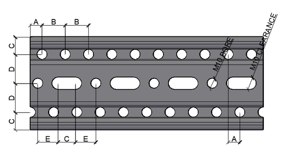 The slot and hole pattern has M10 bore holes designed to accommodate the M10 self forming screw FLS. There are two sets of external holes positioned at 20mm centers and offset from each other by 10mm. This pattern is repeated on all four faces of the profile so that the offset hole position is present on all adjacent sides.
- The slot dimensions of standard components
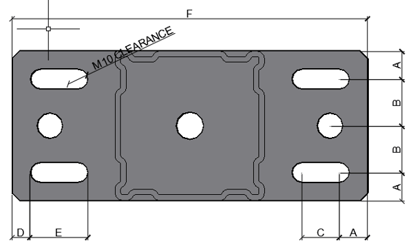
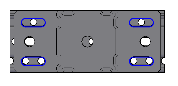
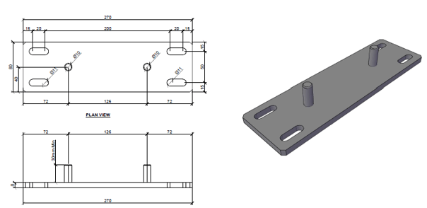
Using the example of an AK-F80 Cantilever baseplate, all standard components within the Framo range use the same 0.5 x 1" slot. On smaller components such as GPL Mounting Plates two such slots are used, on larger components such as the AK Cantilever four slots are used.
- Working together to cater to unrestricted connection positioning
 The combination of the offset hole pattern and 0.5 x 1" slot of the baseplate means that you will always have at least 4 fixing positions for the M10 FLS screws to be located. This allows for millimetre specific accuracy along the entire length of the supporting member.
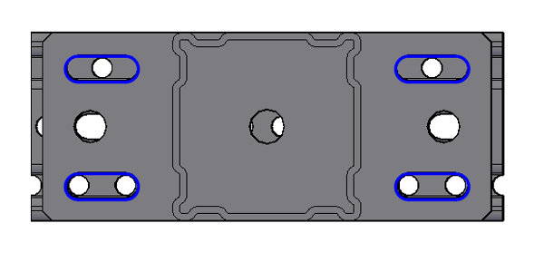
This level of adjustability remains present on all sides of the section, regardless of the position of components on adjacent sides. The offset in hole positioning, in combination with the 0.5 x 1" slot, allows for components to be connected at any point on any face of the profile as indicated in the image below.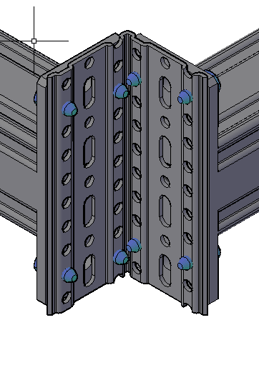
Is this flexibility still true when incorporating non-standard and non-siFramo connections?
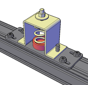
The siFramo system can retain this level of flexibility even when interfacing with non-Sikla support systems and products. Our engineering team have a long history of designing bespoke interface plates/components for items such as anti-vibration mounts, non-Sikla pipe shoes, spring hangers, cable trays/ladders and GRP flooring products.
If the existing hole/slot pattern cannot be directly utilized then, by incorporating the 0.5 x 1" slot that is present in our standard product range, any custom connection we design will have the flexibility to connect anywhere along the siFramo beam section.
Maximum flexibility, simply executed
The siFramo system provides unrestricted connection positioning through the combination of two simple elements:
- An offset M10 bore hole pattern on the extremities of the profile
- An 0.5 x 1" slot on all standard siFramo products
Through the application of these design elements a completely unrestricted fixing position is achievable on any face of the profile, regardless of the components that are affixed to the adjacent faces of the profile.
Coming up next - don't miss it:
- Is independently tested load data available for all components and parts of the system?
- Is test data available for typical frame configurations and based on all 3 possible load directions?
- Is the system BIM and plant design software compatible?
- Can the system be calculated with a 3D structural frame analysis program?
- Is a global manufacturer accountable for the product?
Are you interested in the siFramo system and want to know more about how it could benefit your project?


Comments