Industrial projects face the challenge of low repetitiveness in design, especially in the last stages of detailed design, which usually includes secondary steel supports for piping, ducting and cable services.
Detail designer’s productivity often depends on how quickly she or he can make the right decision about size of profile and connection method. Lack of information or experience can result in over-sizing or under-sizing, neither of which is desirable.
Following our blog series about siFramo modular steel structures key points, this article will introduce our Technical Guidelines and their application under the following topics:
- Typical frame configurations
- Typical loading scenarios
- Working loads and deflections
- How to apply working loads?
- How to check suitability of a typical support loaded in all 3 directions?
Typical frame configurations
At Sikla, we recognised the most common frame configurations and decided to release Technical Guidelines as a practical handbook for designers of secondary steel structures.
Statistically, more than 75% of industrial piping supports can be efficiently designed using these guidelines and all CE marked systems are subject to the certified factory production control according to EN1090 and may therefore be used to EXC 2 for load-bearing structures.
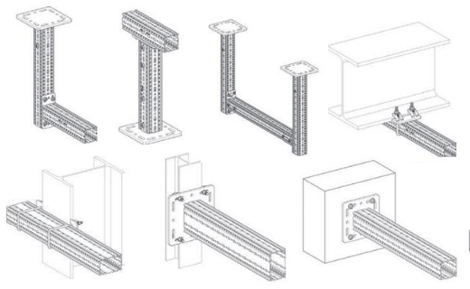 Typical frame configurations
Typical loading scenarios
Test data for each typical support is interpreted in a form of working loads in the 4 most common loading scenarios observed in piping, ducting and electrical services and equipment.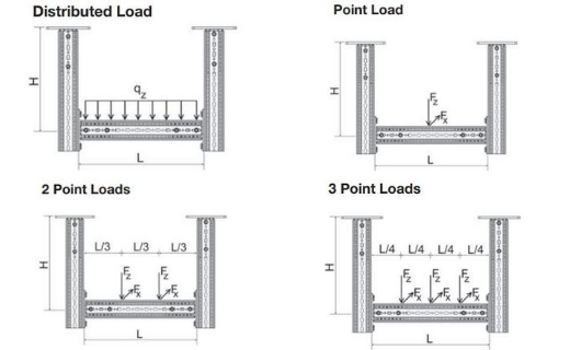
Typical loading scenarios
Working loads and deflection
Working loads are determined based on Eurocode 3 (DIN EN 1993) „Design of steel structures“ and comply with the ultimate limit state and the serviceability limit state design:
- Each component in the technical guidelines was tested to determine its ultimate limit state, as basis for calculating working loads. Results are interpreted for designers in a table format.
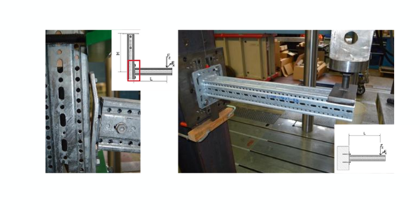
Ultimate limit state testing schematic
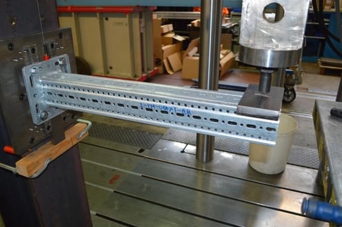
 Ultimate limit state test
- Each typical frame is also tested for serviceability limit state to make sure calculated working loads do not result in an excessive deflection.
Serviceability limit state testing schematic
Serviceability limit state test
How to apply working loads?
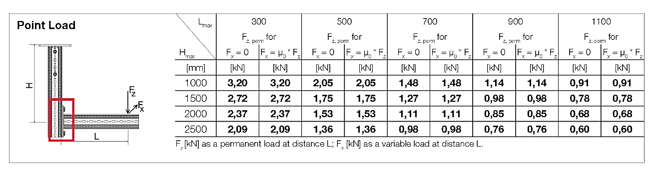
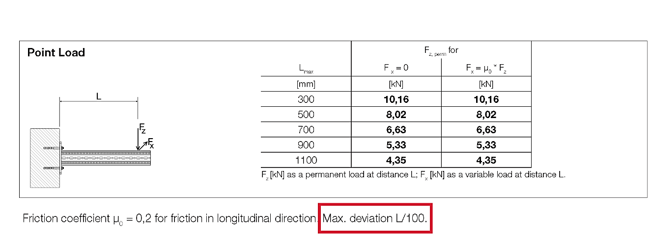
Each typical support has specified governing load Fz, perm which represents the maximum working load a typical frame is designed to bear in vertical direction whilst complying with deflection limits. In practice, it can be the maximum weight of piping that can be supported by a typical support.
 Single working load Fz, perm
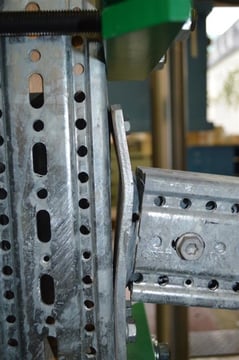
Typical supports can also withstand additional force Fx acting in longitudinal direction simultaneously with vertical Fz, perm. Working load Fx can be calculated as 20% of the Fz, perm. A practical example would be Sikla guided pipe shoe on siFramo beam section thanks to guaranteed friction coefficient μ0 = 0.2.
 Working loads Fz, perm and Fx
Applying these guidelines will ensure frames are exposed to safe working loads and deflection stays within limits specified for each typical frame configuration.
How to check suitability of a typical support loaded in all 3 directions?
Whilst components have been tested in all three directions of loading, providing working loads in all three directions for each typical frame would create too many variations. That would make the guidelines clustered with data in which it would be hard to find the right information.
Such scenario often applies to fixed point support positions which do not allow for any degree of freedom of movement. For such instances we have trained engineers who can perform numerical calculation methods using the right software to determine the most efficient design.
Follow us on LinkedIn or subscribe to our monthly newsletter and learn more about structural analysis of our product in the next article!
Coming up next - don't miss it:
- Can the system be calculated with a 3D structural frame analysis program?
- Is the system BIM and plant design software compatible?
- Is a global manufacturer accountable for the product?
Are you and your team interested in learning more about the Modular Steel Framing System siFramo?
At Sikla we frequently run CPD training sessions. Sign up here to register your companies interest today!
Comments