What is siFramo modular steel and when to use it? When designing a new project, would a modular steel system like this qualify as suitable alternative?
If you are a planning designer or engineer, these are probably your main questions around the decision whether to include or not siFramo in your project. Is this a good guess?
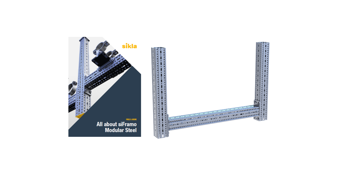
Well, aiming to help you with this decision, our team has been writing several detailed articles about the topic. The main key points about siFramo Modular Steel are now compiled in this article!
Save this page or download now your FREE E-BOOK!
What is siFramo and what was its initial goal?
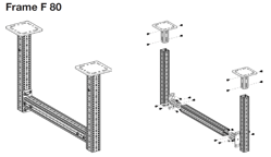
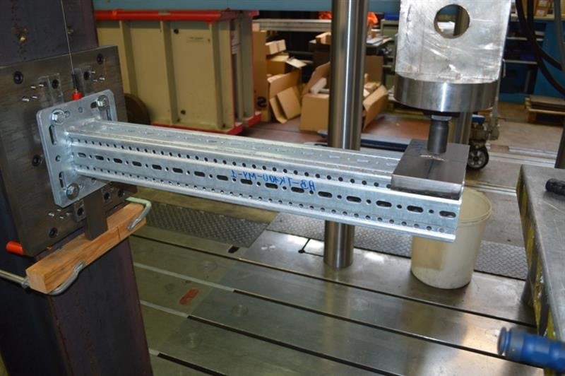
siFramo is a modular steel framing system. It is made of a compact, off-the-shelf readily available range of components, which is connected with a single type of screw.
In 2006, Sikla introduced the first generation of the ‘siFramo’ system, at the time a unique substitute for welded secondary steel. By then it was the only technically acceptable alternative to welding, when supporting pipework and cable containment beyond the load capacity of what is still commonly referred to as ‘Unistrut’.
Avoiding hot works in secondary steel structures was therefore the initial goal of this system, being this one of its main benefits, as stated below:
What are the benefits of siFramo modular steel?
- Significant weight saving
- Engineered frame configurations as standard
- No need for Hot Works
- Easy adjustments can be made on site, eliminating waste
- Connection to most surfaces
- One type of screw for all connections
- EN 1090-1 Compliant Products and Production Control
Check this brochure: have a visual and practical overview of siFramo range and benefits!
Get the most out of siFramo
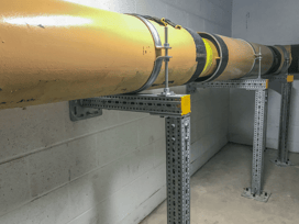
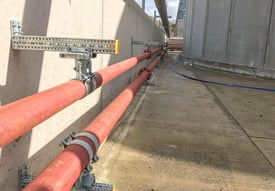
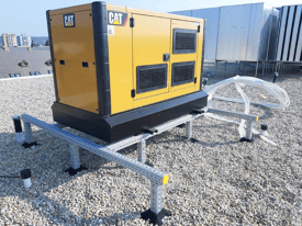
siFramo was first developed to allow pipe support frames for industrial projects. But this concept has grown. It soon became apparent that the application of the system benefit many other construction arrangements. This is the reason why today you can identify the yellow Sikla end caps in a variety of applications and industries.
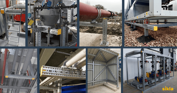
The siFramo steel framing system together with Sikla's pipe supports solutions can be integrated in early stages of your project, in many different areas. Check out now some of the main industries where where we can support you with a dedicated and experienced in-house team of designers and engineers:
There is in fact a wide variety of applications for this system: multi-service modules, plantrooms, roof top plant equipment, support frames, data centre modules, pipe bridges, shelters, access walkways & platforms are just some examples.
Have a look at our project photo gallery and find some great examples!
"How can I know more about the design process and requirements?"
Following this more generic presentation of our modular steel system, here are the important technical details you absolutely need to know:
1. Why are angle brackets too simple as a connection method?
Why modular steel design is more than just bolting an angle bracket to a perforated structure? One of the most important technical details in siFramo’s original FSD (Functional Specification Document) is solidity and stiffness of member connections in all possible loading directions.
Is the connection method all about loading?
If this were all about loading, surely a simple angle bracket, or a multiple arrangement with one bracket in each load direction would do it! However, there is another important requirement derived from traditional pipe rack design, one that applies to electrical containment alike: space management.
No doubt, a welded corner connection within a steel frame is not space consuming and does allow both a pipe shoe and a cable ladder to be placed right into the corner area. A connection based on bolted corner brackets on the other hand needs that area for, guess what, the corner bracket itself.
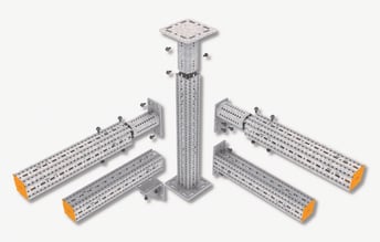
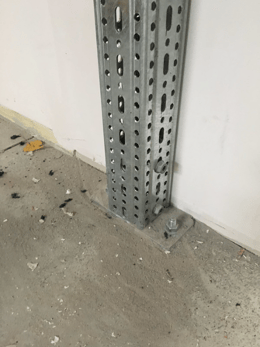
siFramo is generally based on the principles of quality and geometry.
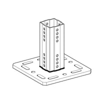
Square and Octagonal end plates (End Support STA and End Support WBD) to apply at the end of a beam section or bracket.
(End Support WBD and End Support STA to apply at the end of beam section or bracket.
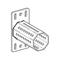
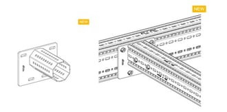
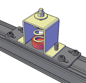
The member to member connections of the siFramo system are based on symmetrically shaped connectors that ‘plug into’ the section rather than being attached to the outside. There are square shaped and octagonally shaped components. As a result, the connection is equally strong in all directions by using just one standard component.
 siFramo square circling in action: high load bearing in all directions but flexible, adjustable and with exchangeable components.
An angle bracket, as well as a webbing piece, are simpler products to design and an easier product to manufacture, the shape is comparably crude, and the manufacturing tolerances are generous enough to find fabricators quickly and globally. However, they lead to a system that misses one of its key details. Both angle brackets and webbing pieces support one part of the connection only and leave other parts of the same connection unsupported.
Therefore, angle brackets are too simple a connection method for a proper modular steel system!
2. Are small parts - as a self-forming screw - safe against confusion, vibration and wrong application?
|
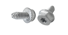
What makes the siFramo modular steel system so unique? Believe it or not, it’s the smallest part of the system: the screw! The system is easily put together with each connection needing a single type of screw. |
 |
Comparing to generic channel systems for example, you often need to consider two elements:
- Spring nut with variable spring lengths (short and long)
- What thread maybe needed to make a connection, from M6 to M16
With the siFramo system, only one type of screw is required for every connection (different profile dimensions and load ranges) thus eliminating any confusion about what is needed to make the connection! The FLS screw as we call is a Self-Forming screw which creates its own thread inside the wall of the siFramo section, in one of the available non-threaded perforations.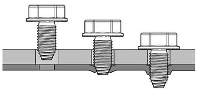
When installed with an Impact Driver (the preferred method of installation) the steel is re-shaped and hardened to form an air-tight seal between the screw threads and surrounding steel of the siFramo section.
This makes it exceptionally resistant to becoming loose from vibration for example and increases the strength of this type of fastening and is made from a very high grade of steel.
Your project will benefit with a simple and effective assembly, by requiring only one type of screw which:
- Avoids confusions about what components to use for the connections
- Benefits the structure with high resistance to vibrations
- Is versatile and applicable to several external contexts and conditions
3. How to perform the quality check of a safe Bolted Connection?
Any standard bolt that may look tightened might in fact not be. In that case the connection would ultimately get lose by vibration in any form. The siFramo FLS screw however provides an unprecedented level of safety because when the naked eye can see that it has been used, it proves already that it will do 90% of the job. This is because it cannot come out on its own nor by any vibration. It is in this regard neither dependent on a washer, a nut or even a counter nut but entirely on its own vacuum sealed thread connection.
To assure full compliance with Eurocode 3 (EN 1993) for "Design of steel structures", which Sikla uses as basis for calculation to determine load capacities, it's important to follow specified tightening torques and perform torque checks on regular basis.
How to torque check a bolted joint?
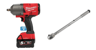
At Sikla, we recognize the importance of torque measurements via static or dynamic methodologies in our own prefabrication process. We use cordless digitally controlled impact wrenches to achieve consistent results and our technicians perform regular quality audits using calibrated torque wrenches.
4. How much of the siFramo steel box section can be used as a support?
In any given industrial application, it is not uncommon to see banks of closely grouped services, be it pipes, cables or ducting, running seamlessly above our heads. So this is the time now to explore 7 ways siFramo can optimise the use of the available space and maximize the use of the profile.
|
From end-to-end |
|
|
With Flat Crossbars |
|
|
With Flat Crossbars |
|
|
With Flat Crossbars |
|
|
By Keeping things Flush |
|
|
By Keeping things Flush |
 |
|
By Keeping things Flush |
 |
So how much of the siFramo Steel section can be used as a support?
When designing a frame with siFramo, there are several alternatives to explore and usually more than one suitable solution. The question is really, what are you supporting and how much space do you have? When we know this, siFramo can be configured to suit your needs, optimise the use of available space and maximise the use of the profile.
5. Can connections be made anywhere along the beam section?
To put it simply, YES, the siFramo modular steel system allows the user to make a connection anywhere along the profile.
There are no incremental fixing positions to worry about during the support design, no slot patterns to observe and therefore no controlled cuts need to be made. As the siFramo system is a steel box section the same level of flexibility has been designed into all four sides of the profile. This allows for unrestricted connection positions in both two dimensional and volumetric supports.
How does the system achieve this?
The big question at this point is, how has the siFramo system been designed in a way to make this possible? It boils down to the combination of two simple elements:
|
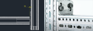
The slot/hole pattern of the profile |
The slot dimensions of standard components  |
|
Working together to cater to unrestricted connection positioning |
|
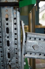
This level of adjustability remains present on all sides of the section, regardless of the position of components on adjacent sides. The offset in hole positioning, in combination with the 0.5 x 1" slot, allows for components to be connected at any point on any face of the profile as indicated in the image below.
Is this flexibility still true when incorporating non-standard and non-siFramo connections?
The siFramo system can retain this level of flexibility even when interfacing with non-Sikla support systems and products.
If the existing hole/slot pattern cannot be directly utilized then, by incorporating the 0.5 x 1" slot that is present in our standard product range, any custom connection we design will have the flexibility to connect anywhere along the siFramo beam section.
6. Easy access to the essential Load Capacity Data
One question that is asked by clients throughout the many industries Sikla works within is: "Do you have load data available?" Our answer to this is: YES!
And why is load capacity data important?
When designing non-structural frames, the Engineer must apply the calculated Action Effects from the Imposed Loads in order to select the correct member section and connection methods. There are 2 methods to obtain section capacity:
- Through calculation from the appropriate local Standards
- Through test data conducted in an accredited laborator
Each method will provide the Engineer with the capacity data for the members and connecting components, allowing them to select the correct design in each case to withstand the Action Effects.
Sikla has its own Technical Guidelines which look at typical support arrangements like goalposts, T-Supports and Cantilevers, and common loading scenarios such as Single and Multiple Point Loads and UDL’s.
What is Independently Tested Capacity Data?
Sikla has worked directly with KIT (Karlsruhe Institute of Technology) in order to independently test our SiFramo beam section and range of components. Examples of these testings are illustrated in the following images, showing torsion and bending tests of siFramo components.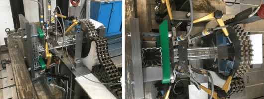
7. Typical frames configurations guidelines
Industrial projects face the challenge of low repetitiveness in design, especially in the last stages of detailed design, which usually includes secondary steel supports for piping, ducting and cable services.
Detail designer’s productivity often depends on how quickly she or he can make the right decision about size of profile and connection method. Lack of information or experience can result in over-sizing or under-sizing, neither of which is desirable.
At Sikla, we recognised the most common frame configurations and have available Technical Guidelines as a practical handbook for designers of secondary steel structures. Statistically, more than 75% of industrial piping supports can be efficiently designed using these guidelines.
Typical loading scenarios
Test data for each typical support is interpreted in a form of working loads in the 4 most common loading scenarios observed in piping, ducting and electrical services and equipment.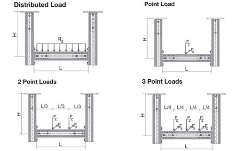
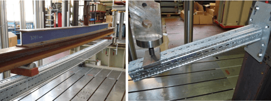
Working loads and deflection
Working loads are determined based on Eurocode 3 (DIN EN 1993) „Design of steel structures“ and comply with the ultimate limit state and the serviceability limit state design:
 |
 |
|
Ultimate limit state test |
Serviceability limit state test |
How to check suitability of a typical support loaded in all 3 directions?
Whilst components have been tested in all three directions of loading, providing working loads in all three directions for each typical frame would create too many variations. That would make the guidelines clustered with data in which it would be hard to find the right information.
Such scenario often applies to fixed point support positions which do not allow for any degree of freedom of movement. For such instances we have trained engineers who can perform numerical calculation methods using the right software to determine the most efficient design.
8. Is the system BIM and plant design software compatible?
This is a question we are asked on a regular basis now, especially when engaged during the planning stages of a project. It really doesn’t matter these days what type of project you are designing or planning: Sikla has a solution for you to streamline your design process and take into consideration BIM (Building Information Modelling).
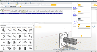
How to integrate Sikla products into BIM tools?
Sikla promotes the use of Building Information Modelling (BIM) to assist project planning, execution and handover. Furthermore, the aim is also to directly implement the Sikla product range into the BIM software tools (e.g. Autodesk Revit, MicroStation etc.). The use of BIM at Sikla will guarantee better project coordination and the reliable execution and completion of projects, keeping with deadlines at constant prices and in line with the highest possible planning standards.
At Sikla, we now have full coverage of the some of the most used CAD applications (summary below):
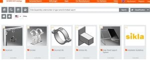
In addition, we have two important resources:
| CADENAS | Free CAD Portal |
 |
 |
Learn more here about this topic: How to plan your project with Sikla software design tools.
9. Designing siFramo modular steel with 3D structural analysis program
As we know, whilst typical configurations are great and cover a large percentage of support positions, there are always instances where designs need an extra level of creativity. This is generally down to one or more of the following conditions:
- Limited or unavailable primary structure thereby limiting fixing opportunities
- Dynamic loading conditions (wind/live load/dynamic pipe forces)
- Service density and layout
In the above situations, the designed support position can take on unusual geometry and be subject to dynamic loads from differing sources. In situations like this being able to utilize the appropriate structural modelling software is paramount to the checking and verification of the supports. For this purpose, the Sikla Group has partnered with Dlubal Software GmbH and use their structural modelling package RSTAB (learn more here about our software design tools).
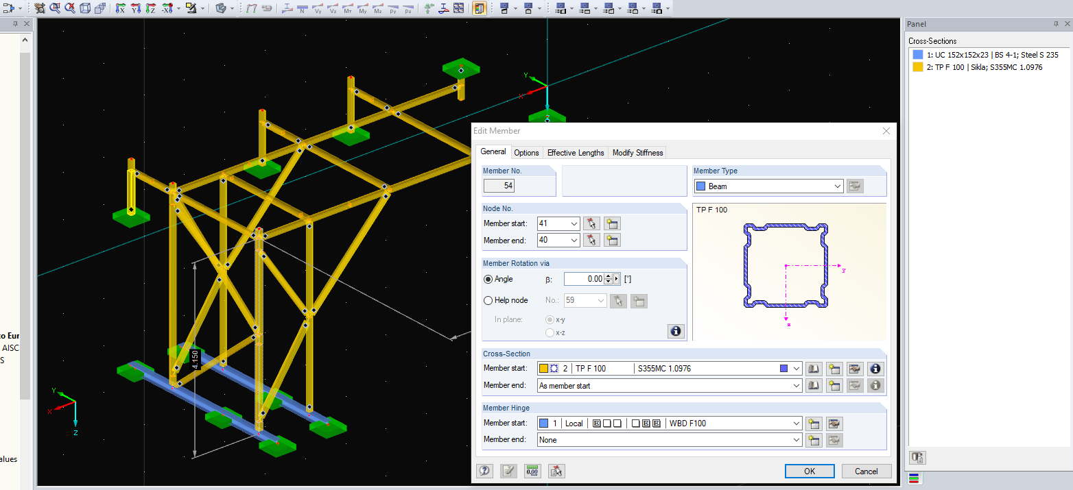
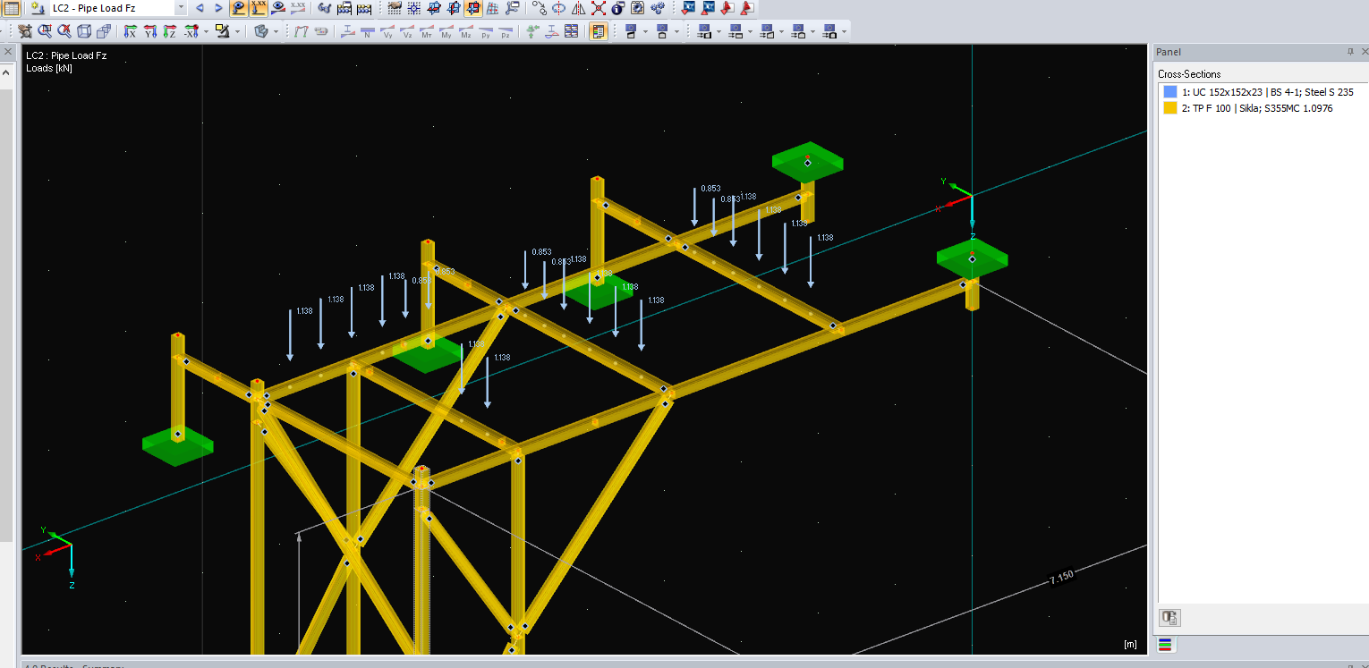
How does the structural modelling software work?
With RSTAB you can easily and quickly define a structural model and then calculate the internal forces, deformations, and support reactions. We split the process up into three sections:
|
1. Modelling of the structure: |
|
|
2. Loading of the structure: |
|
|
3.Review of the structure: |
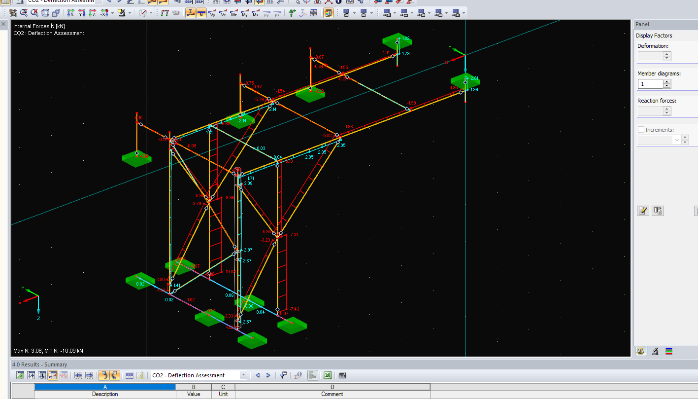 |
And what does this mean for you?
Having confidence in the validity and safety of more complex designs is a key element in being able to supply large scale projects. With sound technical back up clients can rest assured that the siFramo system adheres to the proper design codes, and that the safety of both the project and those who work there will be secure!
So, now our final point: luxury or accountability?
Sikla engineers who have been involved with testing, development, project design and practical application of siFramo have been giving you an insight into some of the most relevant details that have made this system a viable and widely accepted secondary steel solution in industrial plant engineering.
After reading the article, what do you think of siFramo as a branded product?
Over at least two decades it has become some form of normality for certain companies to copy the design of light weight brackets and strut channel systems from established manufacturers, offering ever cheaper deals on installation consumables. End-users tend to focus on generic geometry and comparable prices such as ‘per metre’, ‘per length’ or ‘per 100 pc’ rather than questioning raw material used, available certificates, intrinsic technical data, let alone comparing prices for solutions on a full cost basis.
This mentality has been working for such a long time because of relatively low risks in typical application areas of brackets and lightweight steel on one hand and high safety margins used by branded product manufactures on the other hand.
Applying the same philosophy to heavy duty is shifting business risk from ‘financial’ to ‘operational’. What do we mean? ‘Financial’, i.e. the risk of losing profit margins or tenders due to higher buying prices, toward ‘operational’, i.e. the hazard risk associated with a heavy-duty steel support solution that is potentially not fit for purpose.
A Branded Product is not About Luxury but Accountability
For the best part of 10 years we have been focusing on a particular type of power plant where secondary steel design is challenging, pipe temperatures are high and so are cable weights. The first projects we supplied have undergone conversions and extensions. Plant operators find the name Sikla on all our components and, wherever they are in the world, they find us or at least an authorized representative.
Design from our product system can be verified as-built, compatibility remains guaranteed and so does the product quality itself whether it is the weld or the coating.
Using a branded product means access to third party test data, software plugins that consider all components and their properties, liability and a strong likelihood that the supplier will still be available even when the buyer of its product is not anymore.
It is no luxury to buy a branded modular steel system but statement of quality, traceability and accountability.
We hope that this piece has been useful for you!
Feel free to read the complete and more detailed articles that we've been referring to and to share it with your team!
Keep being updated with our solutions and best practices recommendations:
- Check the Sikla UK, Oceania or USA LinkedIn pages
- Request us access to our main catalogues and technical guidelines

Comments